What makes a load nonlinear, and why does it matter to a transformer?
A linear load draws current in proportion to the applied voltage, so the current stays a clean sine wave. Most modern electronic loads do not. Switch-mode power supplies in servers and IT gear, variable-frequency drives, LED drivers, UPS rectifiers, and electronic ballasts draw current in short pulses near the voltage peak. Those pulses are the sum of the fundamental 60 Hz current plus a series of harmonic currents at multiples of 60 Hz — the 3rd at 180 Hz, the 5th at 300 Hz, the 7th at 420 Hz, and so on.
Harmonic currents matter to a transformer because losses do not rise in proportion to frequency — they rise faster. Winding eddy-current losses climb roughly with the square of the harmonic frequency, so a 300 Hz current heats the windings far more than the same RMS value at 60 Hz. A transformer sized only for its nameplate kVA can therefore run hot, lose insulation life, and fail early on a heavily nonlinear load even though the RMS current never exceeds the rating. IEEE C57.110-2018 is the recommended practice for establishing how much a transformer can carry when the load current is non-sinusoidal.
How a K-factor rating works
The K-factor is a single number that weights each harmonic by how much extra eddy-current heating it produces. Under UL 1561 it is defined as:
K = Σ (Ih / I1)² × h²
where h is the harmonic order and Ih/I1 is that harmonic’s current as a fraction of the fundamental. Because the h² term grows quickly, high-order harmonics dominate the result. A purely linear load gives K = 1; the more harmonic content, the higher the number.
UL recognizes a standard scale — K-1, K-4, K-9, K-13, K-20, K-30, K-40, and K-50. A K-rated transformer is not simply a derated standard unit; it is built to dissipate the additional heating its rating implies, using measures such as smaller, transposed, or paralleled conductors, more conductor cross-section, and often an electrostatic shield between windings. A standard distribution transformer is effectively a K-1 machine.
Matching the rating to the load
The right rating depends on how much of the connected load is nonlinear and what kind. A rough guide used in practice:
| Rating | Typical application |
|---|---|
| K-1 | Motors, resistance heating, incandescent — linear loads |
| K-4 | Mixed receptacle, HVAC, light electronic content |
| K-13 | Schools, health-care, multiple drives, mixed IT |
| K-20 | Data centers, dense server rooms, heavy electronics |
These are starting points, not code minimums. Where the load mix is known, the K-factor can be calculated from a harmonic survey; where it is unknown or expected to grow, designers commonly specify the next rating up rather than risk an undersized unit.
Why the neutral is the other half of the problem
The third harmonic and its odd multiples — the 9th, 15th, 21st, called triplen harmonics — behave differently from the rest. On a 4-wire wye system they are in phase across all three phases, so instead of cancelling at the neutral point they add. The neutral of a panel serving heavy single-phase nonlinear load can therefore carry more current than any phase conductor — theoretically as much as 173% of the phase current under worst-case conditions.
That is why K-rated dry-type transformers are built with a neutral bus rated for at least 200% of full-load current under UL 1561, and why designers often run a double-size neutral from the transformer to the first distribution point. It is also why NEC 220.61(C) does not permit the usual neutral-load reduction to be applied to the nonlinear portion of a wye-connected load — the neutral has to be sized for current that will actually be there.
Where a K-rated transformer makes sense
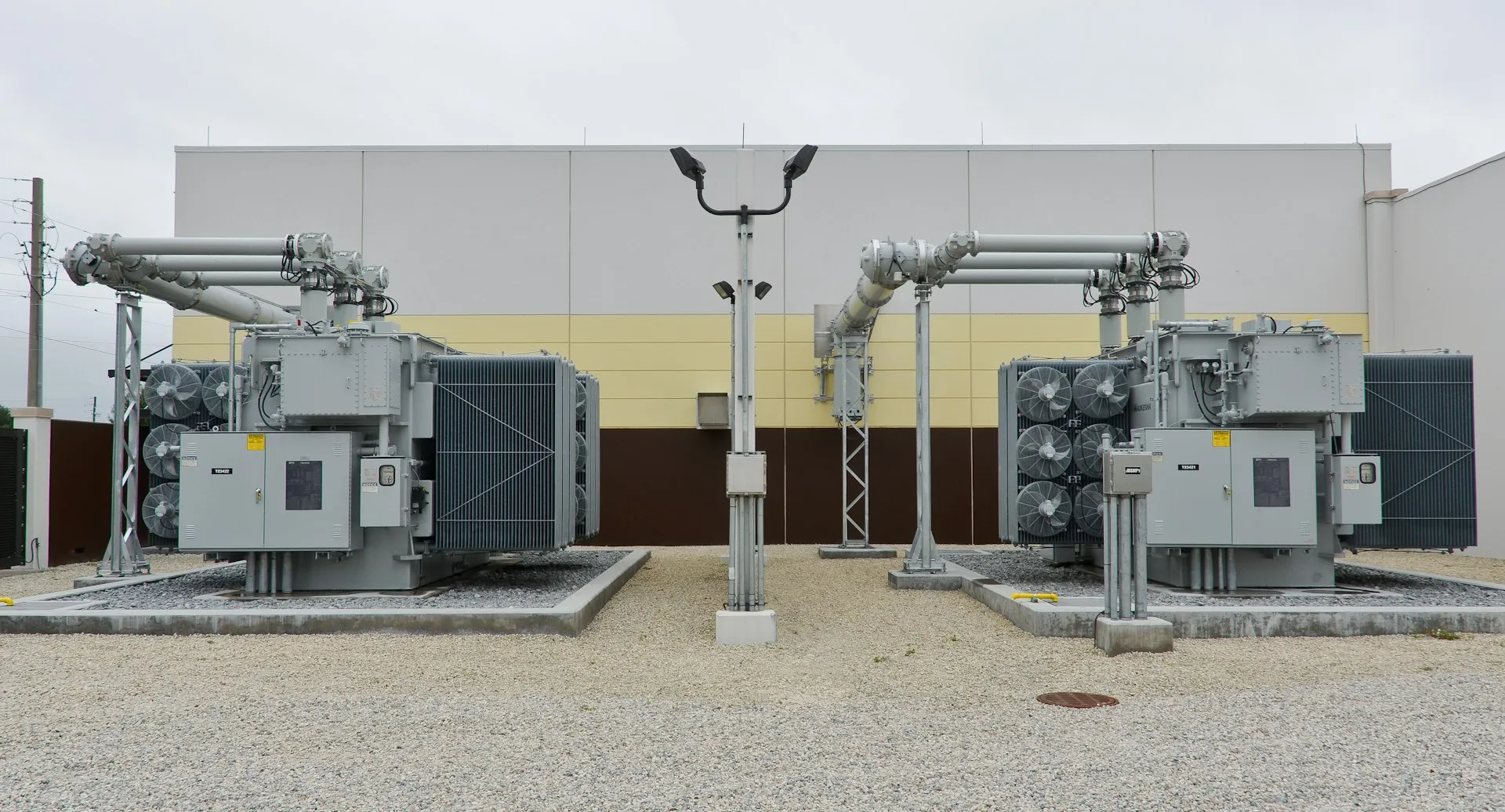
The strongest case is any facility where electronic loads dominate a step-down transformer’s secondary — data centers, trading floors, broadcast and imaging suites, and similar. It is also common on the low-voltage transformers inside substation and power-distribution line-ups feeding modern commercial and industrial buildings, where drives and switch-mode supplies now make up a large share of the load.
Where load is predominantly linear — motors, resistance heating, most HVAC — a standard three-phase dry-type distribution transformer is the correct and more economical choice; a K-rated unit adds cost and mass with no benefit. Low-loss designs such as an amorphous-core dry-type transformer address a different problem — no-load core loss — and are not a substitute for K-rating on a harmonic-heavy load. K-rating is also distinct from power-factor correction: a power-factor-correction capacitor bank trims reactive demand and any utility penalty but does nothing about harmonic heating, and unswitched capacitors can resonate with harmonic currents. The two are specified separately, against different problems.
What a buyer should specify
- The K-rating, from a harmonic survey where possible, or from the load type where not.
- A 200% neutral bus, and where warranted 200% neutral feeders to the downstream distribution switchboard or panelboard.
- The temperature-rise and insulation class, and whether the transformer is evaluated to UL 1561 / CSA C22.2 No. 47 with its capability established per IEEE C57.110.
- Whether an electrostatic shield is required for transient and common-mode-noise attenuation.
Getting the rating right protects insulation life; over-specifying wastes capital. On projects where nonlinear load is the design driver, transformers designed and built to UL 1561 and IEEE C57.110 — with the neutral, shielding, and thermal margin matched to the actual harmonic profile — keep the equipment within its ratings for the life of the load; UL (cULus)/CSA certifiable on request.