Why one nameplate number drives so many downstream decisions
Percent impedance — the %Z stamped on a transformer nameplate — is often treated as a formality, yet it quietly sets the boundaries of the system around the transformer. It determines how much fault current the secondary can deliver into a bolted short, how far the output voltage sags between no load and full load, how two units share load when paralleled, and what short-circuit rating the switchgear and breakers downstream must carry. Choosing it deliberately is a design decision; accepting whatever comes back on a quote is not.
What percent impedance actually measures
Impedance voltage is measured by shorting the secondary and raising the primary voltage until rated current flows. The voltage required, expressed as a percentage of rated primary voltage, is the transformer”s %Z. A 6% transformer needs 6% of rated voltage to push full-load current through a shorted secondary; the internal opposition that number represents is what limits current when a real fault occurs. Because it is a per-unit quantity referred to the transformer”s own rating, %Z carries cleanly into short-circuit and load-flow studies without unit conversions.
How impedance sets available fault current
The relationship every specifier should know is inverse and direct. Ignoring source impedance — the conservative infinite-bus assumption — the secondary short-circuit current is approximately full-load current multiplied by 100 divided by %Z. A 2% transformer therefore delivers roughly three times the bolted-fault current of a 6% unit at the same rating — the multiplier 100 ÷ %Z works out to about 50 times full-load current versus about 17 times. Short-circuit current is inversely proportional to impedance, which means %Z is not only a transformer parameter — it dictates the interrupting rating (AIC) of the breakers and the short-circuit current rating (SCCR) of the panels, metal-clad switchgear, and busway fed from the secondary. Selecting and rating that downstream gear against the calculated fault current is a separate exercise; the point here is that the transformer”s %Z sets the number those ratings must clear. Under-specify %Z and the fault duty can outrun affordable downstream gear; the infinite-bus estimate is intentionally worst-case, because it ignores the utility and cable impedance that would reduce the real number.
The trade-off you are actually buying
Lower impedance is not free. The same internal impedance that limits fault current also drives the voltage regulation drop between no load and full load. A low-%Z transformer holds output voltage tightly and starts motors with less dip, but hands a large fault current to the switchboard. A high-%Z transformer softens fault duty and can ease coordination, but drops more voltage under load and may need a wider tap range or an on-load tap changer to hold setpoint.
- Lower %Z: higher fault current, better voltage regulation, lower motor-start dip
- Higher %Z: lower fault current and downstream SCCR, poorer regulation, more voltage support needed
- The right value balances protective-device ratings against voltage quality for the specific load
Standard values, tolerance, and when to depart from them
Product standards under ANSI/IEEE C57.12 publish preferred impedance values by rating, and most transformers ship near them:
| Transformer size | Typical %Z range |
|---|---|
| Up to ~150 kVA | about 2.0–4.5% |
| ~150–300 kVA | about 4.0–5.0% |
| ~300–600 kVA | about 5.0–5.75% |
| ~600–2,500 kVA | about 5.75–6.5% |
| Above 2,500 kVA | about 6.0–7.0% |
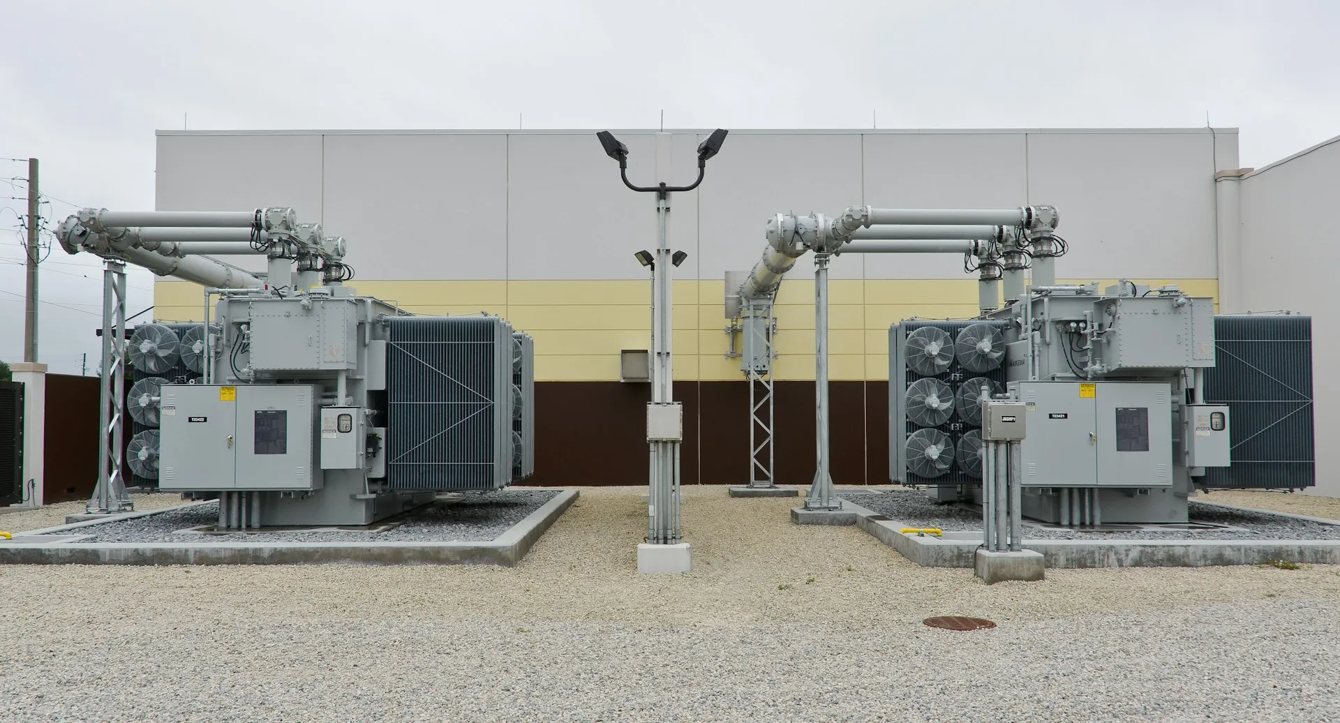
These ranges are governed by IEEE C57.12.00 and C57.12.01, which also fix a manufacturing tolerance — commonly about plus or minus 7.5% for two-winding units, and about plus or minus 10% for three-winding or autotransformer types — so a nameplate 5.75% may test anywhere in a narrow band. Fault studies should use the low end of tolerance for maximum current and the high end for minimum. A non-standard %Z can be specified when the application demands it, but it becomes a design input the factory engineers to, not a value pulled from a catalog. Distribution units such as a three-phase pad-mounted transformer or a dry-type distribution transformer sit toward the lower kVA rows; a 36 kV oil-immersed power transformer or a compact secondary unit substation carries the higher impedances typical of larger ratings.
Paralleling and system coordination
When two transformers feed a common bus, load divides in inverse proportion to their impedances, so the lower-%Z unit takes more than its share and can overload before the other is full. Dependable paralleling requires matched rated voltage, the same vector group and phase displacement, and impedances held close — within tolerance, not merely within the same catalog line. The X/R ratio matters as well: it governs how the fault contribution splits during a short circuit, which relay coordination depends on. These constraints shape substation and distribution layout as much as the ratings themselves.
Where a deliberate impedance choice pays off
- Data centers and other fault-sensitive sites: a slightly higher %Z can keep downstream AIC and SCCR within reach, trading a little regulation for coordinated, economical gear
- Long secondary feeders or voltage-sensitive process loads: lower %Z preserves voltage quality
- Large motor starting: lower %Z reduces starting voltage dip
- Paralleled or redundant banks: impedances matched on purpose so load and fault current split predictably
What a buyer should specify
- Rated %Z and the acceptable tolerance, referencing ANSI/IEEE C57.12.00 as the governing standard
- The downstream SCCR and AIC the secondary fault current must not exceed
- The voltage-regulation target and tap range (or on-load tap changer) needed to hold it at full load
- Vector group and any paralleling requirement, so units are electrically compatible
- Whether a non-standard impedance is required, stated as a design value the manufacturer builds to
Because %Z is engineered into the winding geometry, it is set on the factory floor rather than adjusted in the field — which makes a manufacturer”s ability to build to a specified value part of the specification itself. Entogo”s vertically integrated factory builds transformers and substation and power-distribution packages to a stated impedance, designed and built to ANSI/IEEE C57; UL (cULus) or CSA certifiable on request, and supports the fault and coordination studies behind the number for industrial EPC and data center projects. Teams weighing a value can start from a transformer quote or reach the engineering group through contact.