Where does the fault current go? Grounding as a design choice
Every low- and medium-voltage system has to answer one question before the first fault ever happens: when a live conductor touches ground, where does the current go, and how much of it flows? The answer is fixed by how the system neutral is tied to earth — solidly, through a resistor, or not at all. That single connection decides whether a ground fault trips the main instantly, lets the plant run until a scheduled shutdown, or quietly stresses insulation across the whole system.
On many projects the grounding scheme is inherited from the last job or left to the transformer supplier. For a facility where an unplanned outage is expensive — a continuous process line, a water treatment plant, a data hall — that default deserves a second look, because the three common schemes behave very differently in the same fault.
How do the three schemes behave in a fault?
Solidly grounded
The transformer neutral is bonded directly to the grounding electrode system with no impedance in between. A line-to-ground fault becomes a high-current short circuit that an overcurrent device clears in a fraction of a second. This is the default for any system that also serves line-to-neutral loads — 120 V receptacles, 277 V lighting — because the neutral has to carry normal load current. The trade-off is that a ground fault is a full fault every time, with the associated arc energy and an immediate outage.
Resistance grounded
A neutral grounding resistor (NGR) is inserted between the transformer neutral and ground. In high-resistance grounding (HRG), the resistor limits ground-fault current to a low value — typically 10 amps or less — which is enough to detect and locate the fault but too little to cause escalating damage or force a trip. The plant keeps running on a single ground fault until maintenance finds and clears it. HRG suits three-wire systems feeding motors and process loads, and pairs naturally with the switchgear and motor-control lineups behind an industrial process. Low-resistance grounding allows more current — often hundreds of amps — so protective relays trip selectively, and is common on medium-voltage distribution.
Ungrounded
An ungrounded system has no intentional neutral-to-ground connection. It, too, can ride through a first ground fault, but at a cost. Under arcing or restriking faults the system capacitance charges repetitively, and IEEE 142 (the Green Book) documents transient overvoltages as high as six times normal. Those surges break down insulation at motors and other weak points and touch off second faults elsewhere. That failure mode is why modern practice has largely replaced ungrounded systems with high-resistance grounding, which delivers the same run-through benefit without the overvoltage exposure.
Where does each scheme make sense?
| Priority | Typical scheme |
|---|---|
| 120/208 V or 277/480 V loads, standard commercial | Solidly grounded |
| Continuous process, no line-to-neutral loads | High-resistance grounded |
| MV distribution needing selective relay tripping | Low-resistance grounded |
| Legacy plant being modernized | Convert ungrounded to HRG |
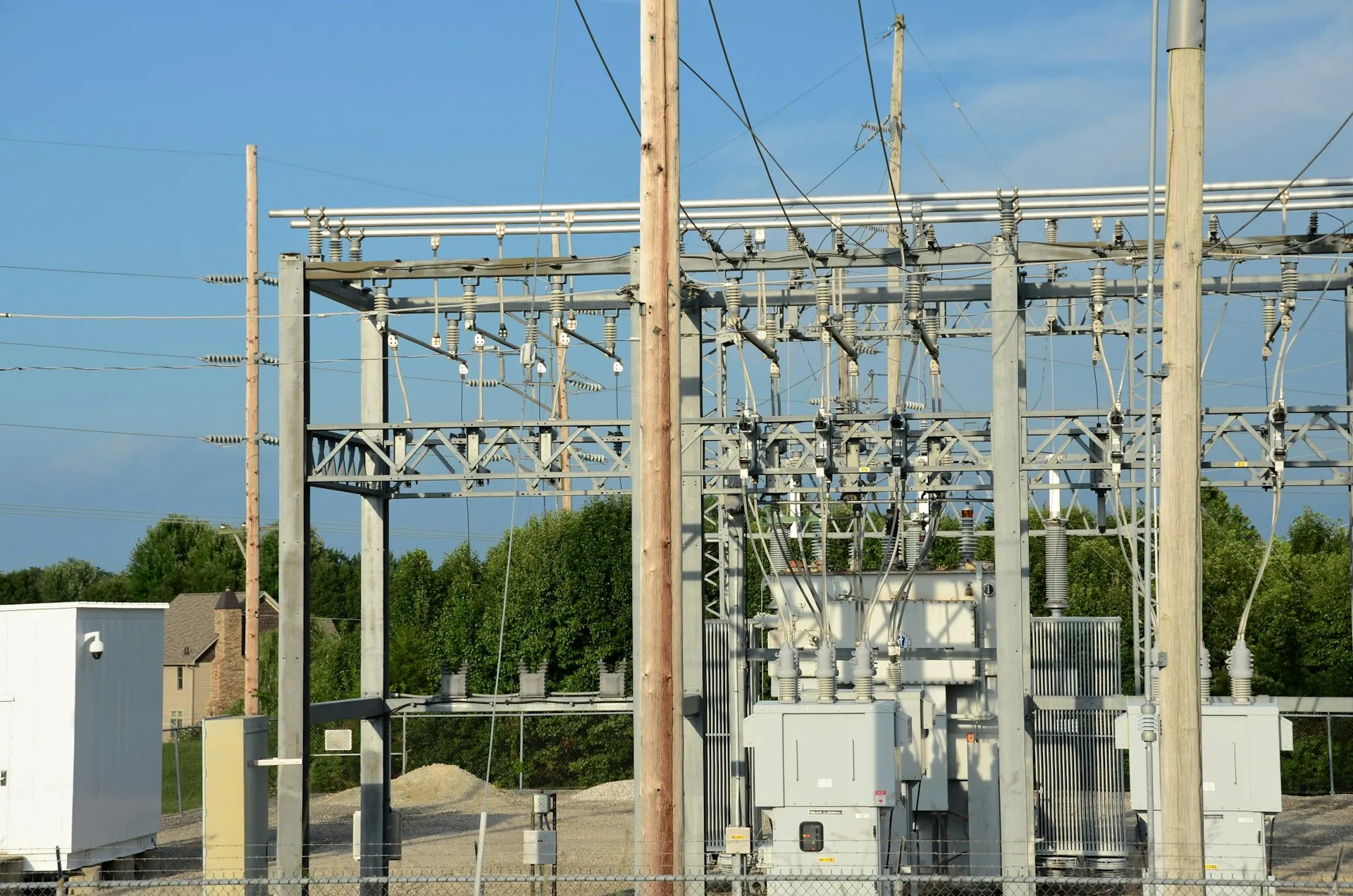
A data center or hospital that needs the neutral for single-phase load is almost always solidly grounded. A refinery or mill that cannot afford a nuisance trip leans toward HRG. Most greenfield medium-voltage work chooses solidly or low-resistance grounding depending on how relay coordination is planned across the substation and distribution lineup.
What should a buyer specify?
Grounding is not a line item added at the end — it is designed into the transformer secondary and the main switchgear together. A specification should state the scheme explicitly and then follow the code and standards that govern it.
- Ground-fault protection. NEC 230.95 requires ground-fault protection of equipment on solidly grounded wye services of more than 150 volts to ground but not exceeding 1000 volts phase-to-phase for each service disconnect rated 1000 amperes or more. Its maximum setting is 1200 amperes, with a maximum time delay of one second for ground-fault currents of 3000 amperes or more. Confirm that the main device in the low-voltage switchgear or MCC carries a GFPE function where the service triggers it.
- High-impedance systems. NEC 250.36 permits high-impedance grounded neutral systems in the 480 V to 1000 V range only where qualified persons maintain the installation, ground detectors are provided, and there are no line-to-neutral loads. Those three conditions belong in the specification, not just on the drawings.
- Coordination context. IEEE 142 governs the wider grounding design — electrode systems, equipment bonding, and sizing of the NGR and neutral conductor. Coordinate the scheme with the protective settings so a fault is caught the way the design intends.
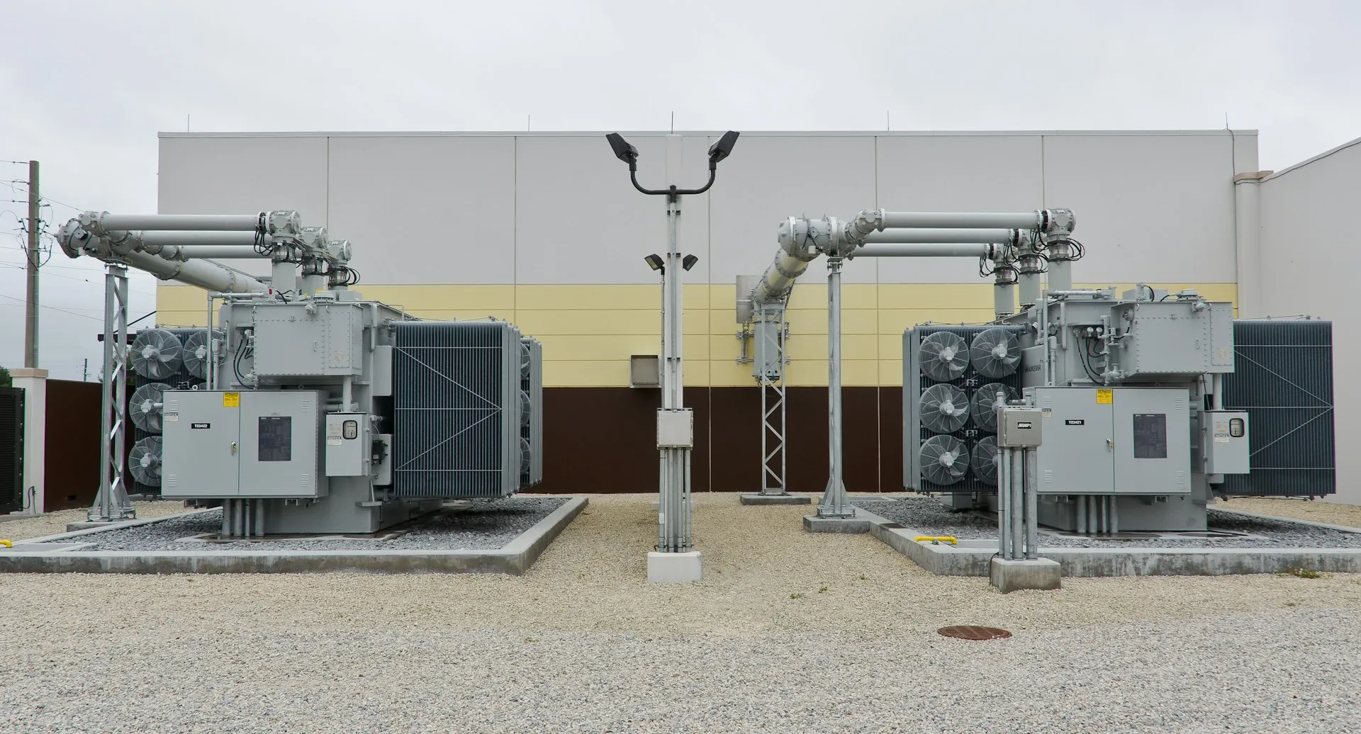
The scheme also has to match the transformer. The neutral point being grounded — solidly or through an NGR — sits on the secondary winding of the oil-immersed power transformer or dry-type unit feeding the building, and on packaged jobs it is set inside the compact secondary unit substation before the equipment reaches site.
How is the scheme built into the equipment?
Because grounding spans the transformer, the neutral resistor, the main switchgear, and the protective relays, it is best resolved as one coordinated package rather than three separately procured parts. Equipment designed and built to the governing standards — ANSI/IEEE C57 for the transformer, IEEE C37 and UL 1558 for the metal-clad switchgear, and the NEC and IEEE 142 for the grounding design — keeps the neutral treatment, the GFPE settings, and the relay coordination consistent from the transformer terminal to the load. Entogo builds transformers, unit substations, and MV/LV switchgear in one vertically integrated factory, designed and built to those standards and UL (cULus)/CSA certifiable on request, so the grounding scheme a buyer specifies is engineered into the lineup rather than reconciled across separate vendors after the fact.