Fleet depots get sized the wrong way round. Someone counts the stalls, multiplies by a dispenser rating, and lands on a service either unbuildable or three times larger than the trucks will draw. A depot is an energy problem first: the trucks need a fixed number of kilowatt-hours back before dispatch, and the question is what power moves that energy inside the window the schedule allows. Thirty Class 8 tractors running 180 miles a day at 2.0 kWh/mi need 10,800 kWh at the batteries, 11,612.9 kWh at the meter, and 1,451.6 kW averaged across an 8-hour window — a 2,000 kVA transformer. The sum of their dispenser nameplates says 2,500 kVA, and NEC 625.42 makes that larger number the code load unless a controller caps it. These are the rules behind the EV charging service capacity calculator.
Why is a depot sized from energy and not from charger nameplates?
A plaza is a power problem: arrivals are random, so every dispenser must meet its rating on demand. At a depot, vehicles, mileage and parked hours are known. Energy binds, power follows.
Daily energy comes from the duty cycle. The National Center for Sustainable Transportation’s review of battery-electric truck studies puts near-term long-haul consumption between 1.3 and 3.8 kWh/mi, narrowing to 1.3–2.5 long term, with NREL’s scenarios at 2.46 and 2.51 kWh/mi for 2018 tractors. A design value of 2.0 kWh/mi sits inside that band.
Two companion articles share the relation P = N × E ÷ (η × t). Sizing a site without a service upgrade takes E as a given (18 kWh in a 200-space Level 2 garage); here E is derived from miles and kWh/mi, which is what changes when the vehicles are tractors. What a DC fast charging site needs converts DC fast charging output kW to AC input kVA for a plaza, where no dwell-time argument applies.
What do NEC 625 and CEC Section 86 require?
| Question | NEC 2023 | CEC (CE Code Part I) |
|---|---|---|
| Is EVSE a continuous load? | 625.42 — yes | 86-302 — the connected load is continuous for Rule 8-104 |
| Device and conductor multiplier | 625.41 — OCPD at 125 % of EVSE rating; also 210.20(A), 215.3 | 8-104(6) — 80 % of rating, or 100 % under 8-104(5) if marked |
| Minimum EVSE load in a service calculation | 220.57 — the greater of 7,200 VA or nameplate | nameplate; no equivalent floor |
| Demand factor on EVSE | none applied here; 220.57 sets the load at the greater of 7,200 VA or nameplate | Table 38 permits demand factors above four EVSE loads, though the ESA subcommittee has recommended deleting it |
| Managed charging | 625.42(A) — controlled load excluded from feeder and service sizing per 750.30(C)(1)(1) | 8-106(10) — demand load equals the EVEMS maximum; 8-106(11) may exclude it for the Rules 8-200 to 8-210 calculations |
| Several dispensers per circuit | 625.40 exception, with an EMS per 625.42(A) or (B) | 86-300 — a separate branch circuit, or a shared one with an EVEMS under 8-106(10) or (11) |
| Controller requirements | 750.30 — must not overload any branch circuit, feeder or service | 8-500(2) — must not exceed 8-104(5) or (6) |
| Transformer and buffer | 450.3(B); storage under Article 706, interconnect 705.12 | 26-254; Section 64 |
NEC 625.42 makes every dispenser continuous, so the unmanaged load is the sum of nameplates with no diversity. 625.42(A) is the only escape.
Worked example — 30 Class 8 tractors on an 8-hour overnight window
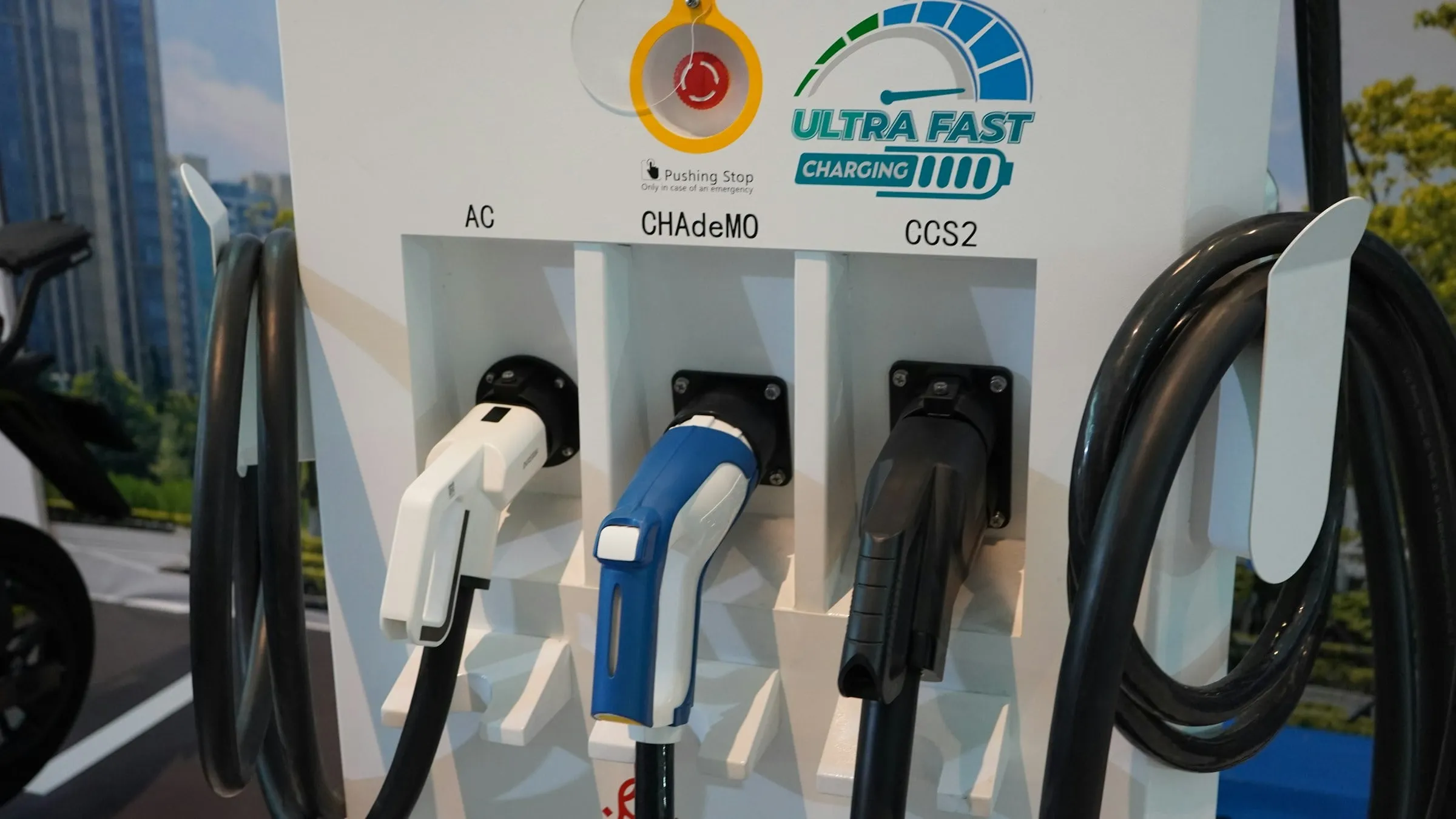
A regional-haul depot outside Toronto. Thirty tractors, 180 mi/day, 2.0 kWh/mi, on the yard at 20:00, dispatched at 04:00. Utility primary 13.8 kV, secondary 480Y/277 V, 160 kW DC dispensers rated at DC output. Assume an AC-input-to-DC-output efficiency of 0.93 session-average (the Rocket DC ultra-fast charger is rated to 95.5 % at its peak, so 0.93 is a deliberate derate) and power factor 0.99, both to be confirmed on the datasheet along with the dispenser’s AC input voltage. The DC plaza article uses η = 0.95, which gives a 1,421.1 kW floor and 1,701.2 kVA for ten dispensers — a 2.1 % spread landing on the same ratings.
- Energy delivered to the trucks. 30 × 180 × 2.0 = 10,800 kWh of DC energy per night.
- Energy at the meter. 10,800 ÷ 0.93 = 11,612.9 kWh. The 812.9 kWh of losses are not optional.
- Average AC power across the window. 11,612.9 ÷ 8 h = 1,451.6 kW — the energy floor; no controller or tariff goes below it while the trucks run 180 mi.
- Apparent power at 80 % loading. 1,451.6 ÷ (0.99 × 0.80) = 1,832.8 kVA.
- Round up the ANSI/IEEE ladder. The next standard three-phase rating is 2,000 kVA.
- Dispenser count. Each tractor needs 360 kWh, or 360 ÷ 160 = 2.25 h. Eight hours fits floor(8 ÷ 2.25) = 3 whole sessions per dispenser, so 30 ÷ 3 = 10 dispensers.
- The unmanaged code load. Ten 160 kW dispensers are 1,600 kW DC, or 1,600 ÷ 0.93 ÷ 0.99 = 1,737.8 kVA at the AC input. Under 625.42 that whole figure is continuous: 1,737.8 ÷ 0.80 = 2,172.3 kVA → a 2,500 kVA transformer, one step above the energy floor.
P = N × d × c ÷ (η × t)
Step 3 — average AC power across the charging window
P = N * d * c / (eta * t)
P = kW
S = P ÷ (PF × L)
Step 4 — transformer kVA floor at 80 % loading
S = P / (PF * L)
S = kVA
h = d × c ÷ Pc
I = S × 1000 ÷ (√3 × V)
At 480 V that is 1,737,800 ÷ (√3 × 480) = 2,090.2 A. NEC 625.41 and 210.20(A) put the main at 1.25 × 2,090.2 = 2,612.8 A, forcing a 3,000 A rating off the NEC 240.6(A) ladder. Add two spare bays and the unmanaged load becomes 2,085.4 kVA, 2,606.7 kVA after the derate and a 3,000 kVA transformer — and 2,508.3 A, which after the 125 % multiplier is 3,135.4 A and a 4,000 A main. Spare bays are cheap; the pad, main and feeder they drag along are not.
A 2,000 kVA unit at 80 % loading and 0.99 power factor delivers 2,000 × 0.80 × 0.99 = 1,584 kW. Against the 1,451.6 kW floor that is 1.091, about 9 % headroom — a cold night or one late truck, not a route extension. Setting the EVEMS ceiling at 1,584 kW is what makes the 2,000 kVA choice legal under 625.42(A), and what makes it tight.
| Design | Code load | Transformer | Main at 480 V |
|---|---|---|---|
| Energy floor only (no code basis alone) | 1,451.6 kW | 2,000 kVA | — |
| 10 dispensers, unmanaged, NEC 625.42 | 1,737.8 kVA | 2,500 kVA | 3,000 A |
| 12 dispensers, unmanaged, NEC 625.42 | 2,085.4 kVA | 3,000 kVA | 4,000 A |
| 12 dispensers, EVEMS capped at 1,584 kW | 1,600.0 kVA | 2,000 kVA | 2,500 A |
| Same, plus a 1,000 kW service limit and buffer | 1,000 kW utility | 1,500 kVA | 1,600 A |
What does the dwell window do to the transformer?
The window is the most leveraged variable here: energy is fixed, so power scales inversely with hours.
| Charging window | Average AC power | kVA at 0.99 PF | At 80 % loading | Transformer |
|---|---|---|---|---|
| 6 h | 1,935.5 kW | 1,955.0 kVA | 2,443.8 kVA | 2,500 kVA |
| 8 h | 1,451.6 kW | 1,466.3 kVA | 1,832.8 kVA | 2,000 kVA |
| 10 h | 1,161.3 kW | 1,173.0 kVA | 1,466.3 kVA | 1,500 kVA |
| 16 h | 725.8 kW | 733.1 kVA | 916.4 kVA | 1,000 kVA |
Moving dispatch from 04:00 to 06:00 takes this depot from 2,000 kVA to 1,500 kVA. NREL’s workshop report notes utilities commonly — though not consistently across all service territories — place a peak limit of 2.5 MW on an interconnection point, owing to a common maximum size of pad-mounted transformers for secondary service. The window is often the difference between a standard service and a utility study; the same report offers 50–500 kW as the span depot charging could cover.
Depot reference table
At 2.0 kWh/mi, η = 0.93, PF = 0.99, an 8-hour window and 80 % loading the divisor is 0.93 × 8 × 0.99 × 0.80 = 5.89248, so kVA = trucks × miles × 2.0 ÷ 5.89248.
| Tractors | Daily miles | Battery energy | kVA at 80 % | Transformer |
|---|---|---|---|---|
| 20 | 180 | 7,200 kWh | 1,221.9 kVA | 1,500 kVA |
| 30 | 180 | 10,800 kWh | 1,832.8 kVA | 2,000 kVA |
| 30 | 250 | 15,000 kWh | 2,545.6 kVA | 3,000 kVA |
| 40 | 180 | 14,400 kWh | 2,443.8 kVA | 2,500 kVA |
| 50 | 180 | 18,000 kWh | 3,054.7 kVA | two 2,000 kVA |
Every row to 3,000 kVA is one pad-mounted unit; the last is a two-transformer lineup. Note that 3,000 kVA is a common manufacturer rating, not a step on the preferred series, where 2,545.6 kVA rounds to 3,750 kVA — see how to size a transformer.
What does the same depot look like in Canada at 600 V?
Voltage and continuous load. At 600 V, 1,737,800 ÷ (√3 × 600) = 1,672.2 A instead of 2,090.2 A, and CEC 8-104(6)‘s ÷ 0.80 gives 2,090.2 A and a 2,500 A main against 3,000 A at 480 V — see choosing a facility distribution voltage. 8-104(5) allows 100 % where the device is marked; the NEC gets there via the 100 %-rated-assembly exceptions to 210.20(A) and 215.3.
Load management is the real divergence. NEC 625.42(A) removes the controlled load from feeder and service sizing. CEC 8-106(10) instead sets the demand load equal to the EVEMS maximum, and 8-106(11) removes it from the calculated load altogether where the EVEMS both monitors the service, feeders and branch circuits and controls the EVSE loads per Rule 8-500 — but only for the calculations enumerated in Rules 8-200 through 8-210, and IAEI advises relying on it only with the local authority’s consent until an EVEMS standard is published. Declare the ceiling as AC input: 1,584 ÷ 0.99 = 1,600.0 kVA, or 1,600,000 ÷ (√3 × 600) = 1,539.6 A, and 1,924.5 A after the 80 % rule — a 2,000 A main. Declared as DC output it would also have to be divided by η. NEC 220.57’s 7,200 VA floor has no CEC counterpart, so Level 2 bays in Canada are calculated at nameplate.
Can a battery buffer hold the service down?
When the utility offers 1,000 kW and the depot needs 1,451.6 kW, storage covers the gap — the peak-shaving duty of cutting demand charges with battery storage, sized by the kW-versus-kWh method in how to size a battery energy storage system. Cap the site flat at 1,451.6 kW, take 1,000 kW from the utility, and the buffer supplies 451.6 kW to the bus for 8 hours.
E = (P − Pu) × t ÷ (DoD × eff)
Buffer usable energy to hold a 1,000 kW service
E = (P - Pu) * t / (DoD * eff)
E = kWh
tr = E × DoD ÷ (eff × Pb)
Buffer recharge time during the 16-hour idle period
tr = E * DoD / (eff * Pb)
tr = h
The shortfall is 451.6 × 8 = 3,612.8 kWh at the bus. At a one-way conversion efficiency of 0.95 the cells give up 3,612.8 ÷ 0.95 = 3,803.0 kWh, and at 0.90 depth of discharge that is 4,225.5 kWh installed with about 500 kW of conversion. Replacing those 3,803.0 kWh costs 3,803.0 ÷ 0.95 = 4,003.1 kWh at the meter — 5.00 hours at 800 kW spare, inside the 16-hour idle period. The 0.95 is paid both ways, so round-trip efficiency is about 0.90, and it is measured, not assumed.
A buffer deferring a service upgrade at a 30-truck depot is therefore a multi-megawatt-hour asset, not a 500 kWh cabinet. The storage is specified against UL 9540 and sited to NFPA 855 — see battery storage fire safety — and its step-up follows battery storage interconnection sizing. A DC-coupled storage and charging system keeps buffer and dispensers on one DC bus.
What to specify
- Daily energy per vehicle, in kWh, and the charging window in hours. Energy from a telematics export or route study, not a brochure range; the window from the dispatch schedule as a guaranteed worst case. Eight hours versus ten is 500 kVA here.
- Charger efficiency, power factor and AC input voltage. From the datasheet at session-average conditions, not the efficiency peak. Assuming 0.95 instead of 0.93 shifts this example by 31 kW.
- The EVEMS ceiling in kW, as AC input, and its fallback state. NEC 750.30 bars the controller from overloading any branch circuit, feeder or service and CEC 8-500(2) from exceeding Rule 8-104(5) or (6); that ceiling becomes the code load under 625.42(A) or 8-106(10).
- Transformer kVA, secondary voltage and %Z. From the transformer sizing calculator and the nameplate — %Z sets the fault current the switchgear clears.
- Main, feeder and interrupting ratings. NEC 240.6(A) after the 125 % of 625.41, or CEC 8-104(6), with the transformer side to 450.3(B) or 26-254 (overcurrent protection) and SCCR to 110.9 from the utility available fault current letter.
- Buffer kW, kWh and depth of discharge. Installed and usable energy quoted separately, under NEC Article 706.
Common mistakes
- Sizing from the nameplate sum and stopping there. Ten 160 kW dispensers read as 1,737.8 kVA and a 2,500 kVA transformer, but the fleet moves only 11,612.9 kWh in 8 hours — 1,451.6 kW average, a 2,000 kVA unit. That sum is the correct code load under NEC 625.42, so the fix is a controller, not a bigger pad.
- Dividing daily energy by 24 hours. 11,612.9 ÷ 24 = 483.9 kW under-sizes by a factor of 3.0 against the 1,451.6 kW the 8-hour window demands. NEC 220.87 allows measured maximum demand on an existing service, never a future load averaged over a day.
- Buying a 500 kWh buffer for a megawatt-hour problem. Holding a 1,451.6 kW depot at a 1,000 kW service needs 4,225.5 kWh at 0.90 depth of discharge — 8.5 times a 500 kWh cabinet.
- Assuming diversity on charger load. NEC 220.57 fixes the EVSE load at the greater of 7,200 VA or nameplate, so the escape is a controller under 625.42(A), not a 0.80 spreadsheet factor. Canada is not symmetrical: CE Code Table 38 does allow demand factors above four EVSE loads, though the ESA subcommittee has recommended deleting it — confirm with the authority first.
Where Entogo fits
Entogo manufactures the depot’s power train in its own roughly 20,000 m² vertically integrated factory — three-phase pad-mounted transformers from 75 to 2500 kVA and up to 3000 kVA at 15/25/35 kV class, low-voltage switchboards for the 1,600–4,000 A mains these calculations land on, and DC ultra-fast chargers at 160/240/300 kW. Equipment is designed and built to ANSI/IEEE C57 and C37, NEC Article 625 and CEC Section 86 as the installation requires; UL (cULus)/CSA certification is available on request. Every product carries a 36-month minimum warranty, with the exact term set per product and confirmed in the contract.
Because transformers, switchgear and chargers are built in the same vertically integrated factory, a depot package can be released against one coordinated submittal rather than chased across three suppliers — which matters when the utility interconnection, not the equipment, should be the critical path. Start from the EV charging service capacity calculator or the transformer configurator; see also EV charging infrastructure.
Depot sizing comes down to four numbers in order: energy delivered to the trucks, energy at the meter, the window it must move through, and the ceiling a controller will enforce. The transformer, main and buffer then follow arithmetically — 10,800 kWh, 11,612.9 kWh, 8 hours, 1,584 kW, and a 2,000 kVA pad instead of a 3,000 kVA one. Take the first number from a brochure instead of the trucks and everything after it is wrong the same way.