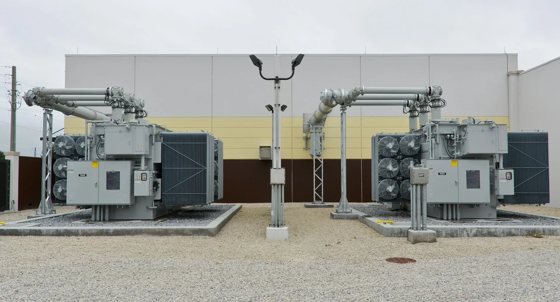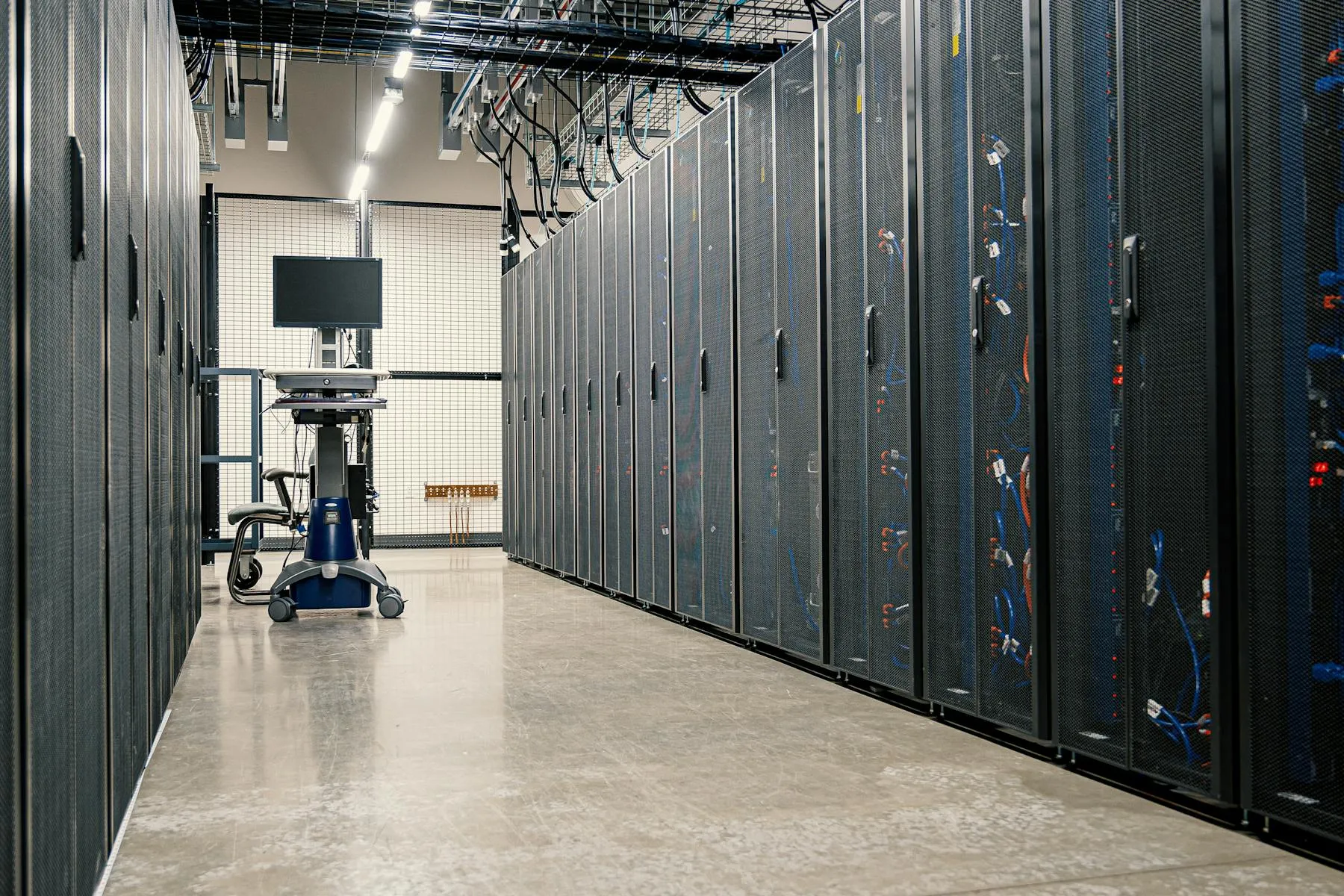
A working AI data center is, before anything else, a power-equipment problem. The silicon arrives — NVIDIA’s GB200 NVL72 racks at around 120 kW each, Vera Rubin NVL144 platforms at roughly 200 kW per rack on a 2026 cadence, Rubin Ultra aiming for 600 kW racks in 2027, OCP’s 2025 keynote unveiling reference racks that draw up to 1 MW. The compute clock is short, and it is set by the vendor roadmap.
The clock that decides whether the campus actually energises in 2026 or 2028 is on the other side of the meter. The U.S. Department of Energy’s July 2024 Large Power Transformer Resilience Report puts current lead times for large power transformers at 80 to 210 weeks — roughly one and a half to four years. Substation packages take longer still. Utility interconnection queues in ERCOT, PJM and Ontario’s IESO have stretched into multi-year backlogs of their own. The binding constraint on the modern AI campus is no longer compute; it is the equipment, the easement and the queue.
The new load profile
Three things distinguish an AI campus from the data-center loads the distribution grid was sized for.
Rack densities have stepped, not climbed. Enterprise IT lived comfortably at 10–15 kW per rack for the better part of two decades. The current Blackwell generation lands at roughly 120 kW per rack; the Open Compute Project’s 2025 reference designs go to 1 MW. The 100 kW rack is now a baseline assumption rather than an extreme case.
Loads are harmonic-rich. UPS rectifiers, variable-frequency drives on the chiller plant, and switch-mode power supplies inside every GPU server all produce non-sinusoidal current. IEEE 519-2014 sets the design framework — broadly an 8% total harmonic distortion limit at the point of common coupling for general industrial users — and transformers serving these loads need a K-factor rating (or an equivalent derating per ANSI/IEEE C57.110) to absorb the heating without losing nameplate capacity.
Loads are dynamic. An AI training job can swing tens of megawatts within seconds when a checkpoint flushes or a job restarts. The protection coordination, the on-load tap changer behaviour, and the response of any battery storage on the bus all need to be designed against the actual load curve, not the steady state.
Rack density, then and now
| Generation | Year | Typical rack power | Cooling regime |
|---|---|---|---|
| Enterprise IT | 2005–2018 | 5–10 kW | Air, hot-aisle containment |
| Pre-AI cloud / colocation | 2018–2022 | 10–25 kW | Air + rear-door heat exchanger |
| Early accelerated compute | 2022–2024 | 25–60 kW | Air + direct-to-chip liquid |
| NVIDIA GB200 NVL72 | 2024–2025 | ~120 kW | Direct-to-chip liquid |
| NVIDIA Vera Rubin NVL144 | 2026 | ~200 kW | Direct-to-chip liquid |
| NVIDIA Rubin Ultra NVL576 | 2027 | ~600 kW (target) | Direct-to-chip liquid |
| OCP 2025 reference | 2025–2027 | up to 1 MW | Direct-to-chip + immersion |
The doubling is not on a Moore-style line; the densities are arriving in steps, each one redrawing the cooling and power architecture below it.
The voltage hierarchy: from utility tie to rack
A 100-megawatt AI campus typically organises its power chain into four distinct voltage stages. Each one has its own dominant equipment, its own constraint, and — in the current market — its own lead time.
| Stage | Voltage class | Typical equipment | What it has to deliver |
|---|---|---|---|
| Utility tie | 115–345 kV | High-voltage substation, GSU transformers | Capacity allocation, fault-level coordination with grid |
| Campus collector | 33 / 34.5 / 35 kV | Prefabricated or built-up substations, GIS switchgear | Distribution across data halls, harmonic and short-circuit handling |
| Building feeder | 11 / 12.47 / 13.8 kV | Indoor metal-clad switchgear, dry-type or oil-immersed step-down transformers | Selective protection, partial-load efficiency at 24/7 duty |
| IT distribution | 480 V (NA) / 415 V (IEC) | Busway, K-rated transformers, UPS | K-factor capacity, very low neutral imbalance, sub-cycle ride-through |
The 33–35 kV “campus collector” layer is where most of the equipment specifications for an AI data center now live, because it is the smallest voltage that can move 100 MW across a multi-building campus without an impractical number of feeders. The transformers and switchgear at that layer are what set the procurement clock.
Transformer specification: where AI loads diverge
Three specifications matter more than the marketing literature suggests.
K-factor. ANSI/IEEE C57.110 defines how a transformer is derated under non-linear load. A standard (K-1) unit feeding heavy IT load runs at approximately 60% of nameplate before winding temperatures exceed insulation class limits. K-13 is the conventional choice for general IT halls; K-20 is specified where industrial VFDs share the bus, common in colocation hyperscale campuses with very large mechanical plants.
Partial-load efficiency. A data center runs near full load nearly all the time. The peak-load efficiency number on a nameplate matters less than the loss curve at 70–90% loading, where the unit will actually spend its life. Specify both no-load and load losses, and verify them against the day-in / day-out load profile, not the design max.
Standard family. IEEE / ANSI / CSA C57 is the North American family; IEC 60076 is the international family. They are similar but not interchangeable — short-circuit testing, tap-changer regimes and impedance tolerances are defined differently. North American projects feeding a NEMA / NEC distribution downstream want IEEE / CSA. Projects following IEC distribution practice (and international colocation operators standardising across regions) want IEC.
| Load type | K-factor recommendation | Notes |
|---|---|---|
| Light commercial IT (offices, edge) | K-4 | Linear LED + light electronic load |
| General data-center IT | K-13 | UPS, switch-mode PSUs dominate harmonic spectrum |
| Hyperscale GPU / training-heavy | K-13 to K-20 | Higher 5th and 7th harmonic content under load swings |
| Mixed IT + industrial VFD (chillers) | K-20 | VFD harmonic content adds to IT spectrum |
(K-factor table adapted from ANSI/IEEE C57.110 derating practice.)
Switchgear, fault levels and the BYOP problem
When a campus adds its own generation — a behind-the-meter gas plant, a fuel cell array, or a multi-megawatt BESS — the fault level at the medium-voltage bus rises. A switchgear lineup specified against a utility-only fault contribution is the most common reason a BYOP retrofit stalls at energisation.
Two design responses are now standard. The first is to specify the 33/35 kV gas-insulated switchgear at the campus collector with a higher interrupting rating than the load demands — typically 25 to 31.5 kA, where 16 kA might have been adequate ten years ago. The second is to wire the BESS and any on-site generation through dedicated current-limiting protection, so their fault contribution is bounded before it reaches the main bus.
Battery storage: ride-through, demand charges and grid services
A 5- to 15-minute lithium-ion BESS sitting on the medium-voltage bus does three things at once on an AI campus.
It provides ride-through for grid events lasting longer than the UPS batteries can cover (typically a few minutes), reducing reliance on diesel or gas backup for short outages. It flattens the load curve seen by the utility, trimming the demand-charge component of the electricity bill — which at hyperscale sites is a structurally large number. And where the utility allows participation, it can offer frequency response or capacity back to the grid, partially monetising the same asset.
The BESS does not replace the UPS. Sub-cycle ride-through (the kind that prevents a job from crashing on a voltage sag) is still the UPS’s job. The two layers complement each other.
Time to power: where the calendar actually goes
The number that ultimately determines when an AI campus serves a workload is time to power, and the breakdown is unforgiving.
| Phase | Typical duration (months) |
|---|---|
| Site selection, easements, environmental review | 6–18 |
| Utility interconnection study & queue | 18–60 |
| Equipment procurement (substation, MV gear) | 24–60 |
| Site civil works | 6–12 |
| Substation construction & commissioning | 4–8 |
| Data hall fit-out & GPU install | 6–9 |
Most of these phases run in parallel. The one that almost always pins the schedule is the equipment procurement line, because none of the others can finish without it. That is the line the EPC team has the most freedom to shorten — and the one most projects shorten last.
Where Entogo fits
Entogo manufactures the transformers, prefabricated substations, medium- and low-voltage switchgear and battery storage that an AI campus depends on, in its own source factory with a vertically integrated supply chain. European-standard (IEC/CE) catalogue equipment ships in an average of 12 weeks — far inside the one-to-four-year merchant-market figures published by the DOE — and within 36 weeks even when a product requires new UL or other North-American certification.
Engagements usually turn into specifications in three steps. An AI data center solution brief defines the campus voltage hierarchy and the equipment shortlist. The transformer side is then configured to ANSI/IEEE C57 or IEC 60076 (an online configurator runs the K-factor, capacity, voltage and cooling selection in five steps). The medium-voltage substation and storage layers follow from the same engineering review.
The compute side of an AI campus moves at the pace of NVIDIA’s roadmap. The power side is now the longest pole. The teams that beat the rest to first revenue do not have a different GPU; they have a power equipment supply chain that is not standing in the merchant queue.